零件
1. ESP8266 ESP-013. 分壓電路/電平轉換器
- 分壓電路電阻 220, 1K x1 , 1.5K/2Kx1, 10K x1
- 電平轉換模組
設定ESP8266
下載
- NodeMCU Firmware
- Firmware Flasher
Win32 Windows Flasher
Win64 Windows Flasher
Linux
https://github.com/themadinventor/esptool
- ESP8266 TCP to Serial Bridge (AP Mode)
- ESP8266 TCP to Serial Bridge (Station Mode)
- ESPlorer
接線圖
使用USB-TTL FTDI
- Jumper 設定為3.3v

使用ArduinoUNO R3
- 要先造好ESP8266 Adaptor
- Adaptor上GPIO0 jumper要接上
- Adaptor VCC -> Arduino 5V
- Adaptor GRN -> Arduino GRN
- Adaptor TX -> Arduino RX0(不要直接接上ESP8266的RX, 會燒的)
- Adaptor RX -> Arduino TX0
- Arduino RST -> Arduino GRN
燒錄NodeMCU步驟
Windows
- 用USB線接上電腦和USB-TTL FTDI
- 開啟Windows Flasher

- 選擇COM Port
- 選擇Frimware

- 之後回到Operation板面,按Flash制
Linux
sudo python setup.py installsudo python esptool.py --port /dev/ttyUSB0 write_flash 0x00000 The_Path_To_The_NodeMCU_Firmware.bin- 請更改
/dev/ttyUSB0和The_Path_To_The_NodeMCU_Firmware.bin ***我用這方法是失敗的,最後找部Windows機來做。。。
加入ESP8266 TCP to Serial Bridge功能
- 打開ESPlorer加入ESP8266 TCP to Serial Bridge的Code (init.lua, File名一定要是init.lua)
- 更改合適的SSID, Wifi Password, IP, Netmask 和Gateway,連線速率改為 115200
- 按Save to ESP8266上傳到ESP8266

連接ESP8266和Arduino/RAMPS 1.4
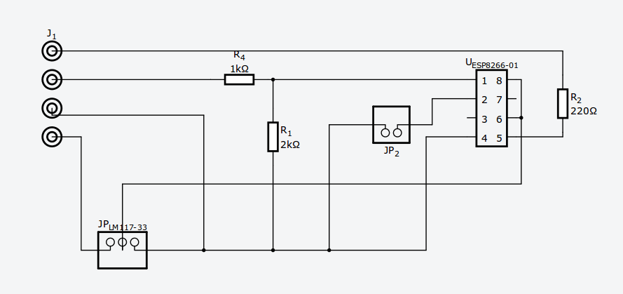
ESP8266 Adaptor
BOM, 另加LM117-33供電模組


線路圖

連接RAMPS
冇用Display - 直接可用Serial2(D16,D17)
| RAMPS | ESP8266 adaptor |
| aux4-D16 | RX |
| aux4-D17 | TX |
| GRN | - |
| + | + |

用LCD-會比較煩
aux4中的D16和D17由LCD佔用,Serial2不能用,而Serial1(D18,D19),Serial3(14,15). 要重新編過, 由於Delta機ZMin同Max多數都要同時使用,所以用Serial3(14,15)會方便少少, 但remap 後x,y endstop各只能用一個如Delta remap後Xmin=YMax, XMax不變,
CoreXY remap後 Xmin=Xmin, XMax=YMin
(其他機種要自己諗諗點Map)
| RAMPS | ESP8266 adaptor |
| Y Min | RX |
| YMax | TX |
| GRN | - |
| + | + |

修改Marlin
1. Configuration.h#SERIAL_PORT X // 冇Display X =2,使用LCD X =3
#define BAUDRATE 115200
2. pins_RAMPS_13.h (用LCD才要改)
Delta 機(使用XMax和YMax)
#define X_MIN_PIN -1 // Disable
#define X_MAX_PIN 2
#define Y_MIN_PIN -1 // Disable
#define Y_MAX_PIN 3
CoreXY 機(使用XMin和YMin)
#define X_MIN_PIN 3
#define X_MAX_PIN -1
#define Y_MIN_PIN 2
#define Y_MAX_PIN -1
改好後接上USB線,upload 到 Arduino Mega, upload之後不能用USB打印, 要用TCP/IP連接
設定Host Software
RepetiveHost1.Printer Settings -> Connector 選TCP/IP Connection
2. IP Address -> 設定ESP8266時輸入的IP
3. Port -> 設定ESP8266時輸入的Port (9876)
Pronterface
未用過, 但好似有相同的setting
其他
Windows 可用 HW VSP3 - Virtual Serial Port 轉駁TCP/IP
http://www.hw-group.com/products/hw_vsp/index_en.html
Linux可用
socat pty,link=/dev/virtualcom0,raw tcp:192.168.0.xxx:9876&
沒有留言:
張貼留言